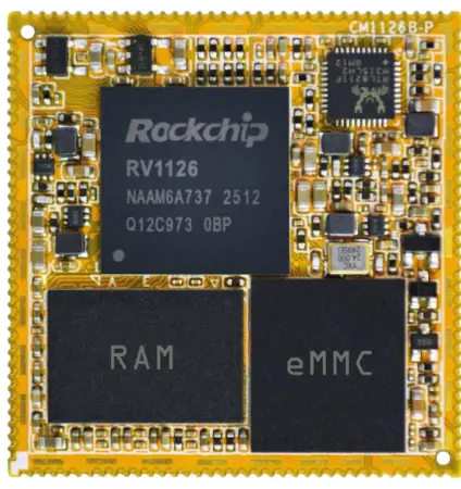
Sistem integrat Boardcon CM1126B-P pe modul
Specificații
| Caracteristică | Specificații |
| CPU | Quad-core Cortex-A53 |
| DDR | 2 GB LPDDR4 (până la 4 GB) |
| eMMC FLASH | 8 GB (până la 256 GB) |
| Putere | DC 3.3V |
| MIPI DSI | 4 benzi |
| I2S | 4-CH |
| MIPI CSI | 2-CH cu 4 benzi |
| LCD RGB | 24 biți |
| Camera foto | 1-CH(DVP) și 2-CH(CSI) |
| USB | 2-CH (USB HOST 2.0 and OTG 2.0) |
| Ethernet | 1000 M GMAC |
| SDMMC | 2-CH |
| I2C | 5-CH |
| SPI | 2-CH |
| UART | 5-CH, 1-CH(DEBUG) |
| PWM | 11-CH |
| ADC IN | 4-CH |
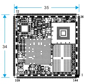
| Dimensiunea plăcii | 34 x 35 mm |
Introducere
Despre acest manual
Acest manual are scopul de a oferi utilizatorului un overview a plăcii și a beneficiilor acesteia, specificațiile complete ale funcțiilor și procedurile de configurare. Conține, de asemenea, informații importante privind siguranța.
Feedback și actualizare la acest manual
Pentru a ajuta clienții noștri să profite la maximum de produsele noastre, oferim în mod continuu resurse suplimentare și actualizate pe Boardcon website (www.boardcon.com, www.armdesigner.com). Acestea includ manuale, note de aplicație, programare de exampfișiere și software și hardware actualizat. Verificați-vă periodic pentru a vedea ce este nou! Când acordăm prioritate lucrărilor cu privire la aceste resurse actualizate, feedback-ul de la clienți este influența numărul unu. Dacă aveți întrebări, comentarii sau nelămuriri cu privire la produsul sau proiectul dvs., nu ezitați să ne contactați la support@armdesigner.com.
CM1126B-P Introduction
Rezumat
The CM1126B-P system-on-module is equipped with Rockchip’s RV1126B-P, built with a quad-core Cortex-A53, 3.0 TOPs NPU, and RISC-V MCU. It is designed specifically for the IPC/CVR devices, AI Camera devices, intelligent interactive devices, and mini robots. High-performance and low-power solutions can help customers introduce new technologies more quickly and enhance the overall solution efficiency. The smallest size can be put on a 38board. Following the hardware revision from CM1126 (V1) to CM1126B-P (V2), where the SoC is updated to the RV1126B-P, the Reset & OTG_VBUS signals and the WIFI/BT module’s GPIO voltagTrebuie să funcționeze la un nivel logic de 3.3V.
Caracteristici
Microprocesor
- Quad-core Cortex-A53 până la 1.6 GHz
- 32KB I-cache și 32KB D-cache pentru fiecare nucleu, 512KB cache L3
- 3.0 TOPS Unitate de proces neuronal
- RISC-V MCU to support 250ms fast boot
- Max 12 M ISP
Organizarea memoriei
- RAM LPDDR4 de până la 4 GB
- eMMC până la 256 GB
- SPI Flash de până la 8 MB
Decodor/Encoder video
- Suportă decodare/codificare video până la 4K@30fps
- Acceptă decodarea în timp real a H.264/265
- Suportă codificare video UHD H.264/265 în timp real
- Dimensiunea imaginii este de până la 8192×8192
Subsistem de afișare
- Ieșire video
- Supports 4 lanes MIPI DSI up to 2560×1440@60fps
- Supports 24-bit RGB parallel output
- Imagine în
- Suportă interfață DVP de până la 16 biți
- Suportă interfața 2ch MIPI CSI 4lanes
I2S/PCM/ AC97
- Trei interfețe I2S/PCM
- Suportă matrice de microfon Interfață PDM/TDM de până la 8 canale
- Suportă ieșire audio PWM
USB și PCIE
- Două interfețe USB 2.0
- One USB 2.0 OTG and one 2.0 USB host
Ethernet
- RTL8211F la bord
- Suport 10/100/1000M
I2C
- Până la cinci I2C
- Acceptă modul standard și modul rapid (până la 400 kbit/s)
SDIO
- Suporta protocolul 2CH SDIO 3.0
SPI
- Până la două controlere SPI,
- Interfață serială sincronă full-duplex
UART
- Suportă până la 6 UART-uri
- UART2 cu 2 fire pentru instrumente de depanare
- Două FIFO-uri de 664 de octeți încorporate
- Suportă modul de control automat al fluxului pentru UART0/1/3/4/5
ADC
- Până la patru canale ADC
- Rezoluție de 12 biți
- VoltagIntervalul de intrare între 0V și 1.8V
- Suportă până la 1MS/ssamprata ling
PWM
- 11 PWM-uri pe cip cu funcționare bazată pe întreruperi
- Support 32-bit time/counter facility
- Opțiune IR pe PWM3/7
Unitate de putere
- Putere discretă la bord
- O singură intrare de 3.3 V
Diagrama bloc CM1126B-P
Diagrama bloc RV1126B-P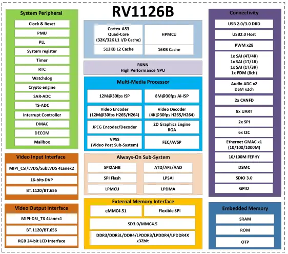
Development board (Idea1126) Block Diagram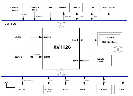
Dimensiunea PCB-ului CM1126B-P
Definiția pinului CM1126B-P
| Pin | Semnal | Descriere sau funcții | Serial GPIO | IO Voltage |
| 1 | LCDC_D19_3V3 | I2S1_MCLK_M2/CIF_D15_M1 | GPIO2_C7_d | 3.3V |
| 2 | LCDC_D20_3V3 | I2S1_SDO_M2/CIF_VS_M1 | GPIO2_D0_d | 3.3V |
| 3 | LCDC_D21_3V3 | I2S1_SCLK_M2/CIF_CLKO_M1 | GPIO2_D1_d | 3.3V |
| 4 | LCDC_D22_3V3 | I2S1_LRCK_M2/CIF_CKIN_M1 | GPIO2_D2_d | 3.3V |
| 5 | LCDC_D23_3V3 | I2S1_SDI_M2/CIF_HS_M1 | GPIO2_D3_d | 3.3V |
| 6 | GND | Sol | 0V | |
| 7 | GPIO1_D1 | UART1_RX_M1/I2C5_SDA_M2 | GPIO1_D1_d | 3.3 V (V2) |
| 8 | BT_WAKE | SPI0_CS1n_M0 | GPIO0_A4_u | 3.3 V (V2) |
| 9 | WIFI_REG_ON | SPI0_MOSI_M0 | GPIO0_A6_d | 3.3 V (V2) |
| 10 | BT_RST | SPI0_MISO_M0 | GPIO0_A7_d | 3.3 V (V2) |
| 11 | WIFI_WAKE_HOST | SPI0_CLK_M0 | GPIO0_B0_d | 3.3 V (V2) |
| 12 | BT_WAKE_HOST | SPI0_CS0n_M0 | GPIO0_A5_u | 3.3 V (V2) |
| 13 | PWM7_IR_M0_3V3 | GPIO0_B1_d | 3.3V | |
| 14 | PWM6_M0_3V3 | TSADC_SHUT_M1 | GPIO0_B2_d | 3.3V |
| 15 | UART2_TX_3V3 | Pentru depanare | GPIO3_A2_u | 3.3V |
| 16 | UART2_RX_3V3 | Pentru depanare | GPIO3_A3_u | 3.3V |
| 17 | I2S0_MCLK_M0_3V
3 |
GPIO3_D2_d | 3.3V | |
| 18 | I2S0_SCLK_TX_M0
_3V3 |
ACODEC_DAC_CLK | GPIO3_D0_d | 3.3V |
| 19 | I2S0_SDI3_M0_3V3 | PDM_SDI3_M0 /
ACODEC_ADC_DATA |
GPIO3_D7_d | 3.3V |
| 20 | I2S0_SDO0_M0_3V
3 |
ACODEC_DAC_DATAR
/APWM_R_M1/ADSM_LP |
GPIO3_D5_d | 3.3V |
| Pin | Semnal | Descriere sau funcții | Serial GPIO | IO Voltage |
| 21 | I2S0_LRCK_TX_M0
_3V3 |
ACODEC_DAC_SYNC
/APWM_L_M1/ADSM_LN |
GPIO3_D3_d | 3.3V |
| 22 | PDM_SDI1_3V3 | I2S0_SDO3_SDI1_M0/I2C4SDA | GPIO4_A1_d | 3.3V |
| 23 | PDM_CLK1_3V3 | I2S0_SCK_RX_M0 | GPIO3_D1_d | 3.3V |
| 24 | PDM_SDI2_3V3 | I2S0_SDO2_SDI2_M0/I2C4SCL | GPIO4_A0_d | 3.3V |
| 25 | PDM_SDI0_3V3 | I2S0_SDI0_M0 | GPIO3_D6_d | 3.3V |
| 26 | PDM_CLK_3V3 | I2S0_LRCK_RX_M0 | GPIO3_D4_d | 3.3V |
| 27 | I2C2_SDA_3V3 | PWM5_M0 | GPIO0_C3_d | 3.3V |
| 28 | I2C2_SCL_3V3 | PWM4_M0 | GPIO0_C2_d | 3.3V |
| 29 | USB_HOST_DP | 1.8V | ||
| 30 | USB_HOST_DM | 1.8V | ||
| 31 | GND | Sol | 0V | |
| 32 | OTG_DP | Poate fi folosit pentru descărcare | 1.8V | |
| 33 | OTG_DM | Poate fi folosit pentru descărcare | 1.8V | |
| 34 | OTG_DET(V2) | OTG VBUS DET IN | 3.3 V (V2) | |
| 35 | OTG_ID | 1.8V | ||
| 36 | SPI0_CS1n_M1 | I2S1_MCK_M1/UART4_TX_M2 | GPIO1_D5_d | 1.8V |
| 37 | VCC3V3_SYS | Intrare de alimentare principală de 3.3 V | 3.3V | |
| 38 | VCC3V3_SYS | Intrare de alimentare principală de 3.3 V | 3.3V | |
| 39 | USB_CTRL_3V3 | GPIO0_C1_d | 3.3V | |
| 40 | SDMMC0_DET | Trebuie folosit pentru cardul SD | GPIO0_A3_u | 3.3 V (V2) |
| 41 | CLKO_32K | Ieșire ceas RTC | GPIO0_A2_u | 3.3 V (V2) |
| 42 | nRESET | Resetați introducerea tastei | 3.3 V (V2) | |
| 43 | MIPI_CSI_RX0_CL
KP |
Intrare MIPI CSI0 sau LVDS0 | 1.8V | |
| 44 | MIPI_CSI_RX0_CL
KN |
Intrare MIPI CSI0 sau LVDS0 | 1.8V | |
| 45 | MIPI_CSI_RX0_D2
P |
Intrare MIPI CSI0 sau LVDS0 | 1.8V | |
| 46 | MIPI_CSI_RX0_D2
N |
Intrare MIPI CSI0 sau LVDS0 | 1.8V | |
| 47 | MIPI_CSI_RX0_D3
P |
Intrare MIPI CSI0 sau LVDS0 | 1.8V | |
| 48 | MIPI_CSI_RX0_D3
N |
Intrare MIPI CSI0 sau LVDS0 | 1.8V | |
| 49 | MIPI_CSI_RX0_D1
P |
Intrare MIPI CSI0 sau LVDS0 | 1.8V | |
| 50 | MIPI_CSI_RX0_D1
N |
Intrare MIPI CSI0 sau LVDS0 | 1.8V | |
| 51 | MIPI_CSI_RX0_D0
P |
Intrare MIPI CSI0 sau LVDS0 | 1.8V |
| Pin | Semnal | Descriere sau funcții | Serial GPIO | IO Voltage |
| 52 | MIPI_CSI_RX0_D0
N |
Intrare MIPI CSI0 sau LVDS0 | 1.8V | |
| 53 | GND | Sol | 0V | |
| 54 | MIPI_CSI_RX1_D3
P |
Intrare MIPI CSI1 sau LVDS1 | 1.8V | |
| 55 | MIPI_CSI_RX1_D3
N |
Intrare MIPI CSI1 sau LVDS1 | 1.8V | |
| 56 | MIPI_CSI_RX1_CL
KP |
Intrare MIPI CSI1 sau LVDS1 | 1.8V | |
| 57 | MIPI_CSI_RX1_CL
KN |
Intrare MIPI CSI1 sau LVDS1 | 1.8V | |
| 58 | MIPI_CSI_RX1_D2
P |
Intrare MIPI CSI1 sau LVDS1 | 1.8V | |
| 59 | MIPI_CSI_RX1_D2
N |
Intrare MIPI CSI1 sau LVDS1 | 1.8V | |
| 60 | MIPI_CSI_RX1_D1
P |
Intrare MIPI CSI1 sau LVDS1 | 1.8V | |
| 61 | MIPI_CSI_RX1_D1
N |
Intrare MIPI CSI1 sau LVDS1 | 1.8V | |
| 62 | MIPI_CSI_RX1_D0
P |
Intrare MIPI CSI1 sau LVDS1 | 1.8V | |
| 63 | MIPI_CSI_RX1_D0
N |
Intrare MIPI CSI1 sau LVDS1 | 1.8V | |
| 64 | SDMMC0_D3_3V3 | UART3_TX_M1 | GPIO1_A7_u | 3.3V |
| 65 | SDMMC0_D2_3V3 | UART3_RX_M1 | GPIO1_A6_u | 3.3V |
| 66 | SDMMC0_D1_3V3 | UART2_TX_M0 | GPIO1_A5_u | 3.3V |
| 67 | SDMMC0_D0_3V3 | UART2_RX_M0 | GPIO1_A4_u | 3.3V |
| 68 | SDMMC0_CMD_3V
3 |
UART3_CTSn_M1 | GPIO1_B1_u | 3.3V |
| 69 | SDMMC0_CLK_3V3 | UART3_RTSn_M1 | GPIO1_B0_u | 3.3V |
| 70 | GND | Sol | 0V | |
| 71 | LED1/CFG_LDO0 | LED Ethernet LINK | 3.3V | |
| 72 | LED2/CFG_LDO1 | LED Ethernet SPEED | 3.3V | |
| 73 | MDI0 + | Semnal Ethernet MDI | 1.8V | |
| 74 | MDI0- | Semnal Ethernet MDI | 1.8V | |
| 75 | MDI1 + | Semnal Ethernet MDI | 1.8V | |
| 76 | MDI1- | Semnal Ethernet MDI | 1.8V | |
| 77 | MDI2 + | Semnal Ethernet MDI | 1.8V | |
| 78 | MDI2- | Semnal Ethernet MDI | 1.8V | |
| 79 | MDI3 + | Semnal Ethernet MDI | 1.8V | |
| 80 | MDI3- | Semnal Ethernet MDI | 1.8V | |
| 81 | I2C1_SCL | UART4_CTSn_M2 | GPIO1_D3_u | 1.8V |
| Pin | Semnal | Descriere sau funcții | Serial GPIO | IO Voltage |
| 82 | I2C1_SDA | UART4_RTSn_M2 | GPIO1_D2_u | 1.8V |
| 83 | MIPI_CSI_PWDN0 | UART4_RX_M2 | GPIO1_D4_d | 1.8V |
| 84 | SPI0_CLK_M1 | I2S1_SDO_M1/UART5_RX_M2 | GPIO2_A1_d | 1.8V |
| 85 | SPI0_MOSI_M1 | I2S1_SCK_M1/I2C3_SCL_M2 | GPIO1_D6_d | 1.8V |
| 86 | SPI0_CS0n_M1 | I2S1_SDI_M1/UART5_TX_M2 | GPIO2_A0_d | 1.8V |
| 87 | SPI0_MISO_M1 | I2S1_LRCK_M1/I2C3_SDA_M2 | GPIO1_D7_d | 1.8V |
| 88 | MIPI_CSI_CLK1 | UART5_RTSn_M2 | GPIO2_A2_d | 1.8V |
| 89 | MIPI_CSI_CLK0 | UART5_CTSn_M2 | GPIO2_A3_d | 1.8V |
| 90 | GND | Sol | 0V | |
| 91 | LCDC_D0_3V3 | UART4_RTSn_M1/CIF_D0_M1 | GPIO2_A4_d | 3.3V |
| 92 | LCDC_D1_3V3 | UART4_CTSn_M1/CIF_D1_M1 | GPIO2_A5_d | 3.3V |
| 93 | LCDC_D2_3V3 | UART4_TX_M1/CIF_D2_M1 | GPIO2_A6_d | 3.3V |
| 94 | LCDC_D3_3V3 | UART4_RX_M1/I2S2_SDO_M1 | GPIO2_A7_d | 3.3V |
| 95 | LCDC_D4_3V3 | UART5_TX_M1/I2S2_SDI_M1 | GPIO2_B0_d | 3.3V |
| 96 | LCDC_D5_3V3 | UART5_RX_M1/I2S2_SCK_M1 | GPIO2_B1_d | 3.3V |
| 97 | LCDC_D6_3V3 | UART5_RTSn_M1/I2S2_LRCK_
M1 |
GPIO2_B2_d | 3.3V |
| 98 | LCDC_D7_3V3 | UART5_CTSn_M1/I2S2_MCLK_
M1/CIF_D3_M1 |
GPIO2_B3_d | 3.3V |
| 99 | CAN_RX_3V3 | UART3_TX_M2/I2C4_SCL_M0 | GPIO3_A0_u | 3.3V |
| 100 | CAN_TX_3V3 | UART3_RX_M2/I2C4_SDA_M0 | GPIO3_A1_u | 3.3V |
| 101 | LCDC_CLK_3V3 | UART3_CTSn_M2/SPI1_MISO_
M2/PWM8_M1 |
GPIO2_D7_d | 3.3V |
| 102 | LCDC_VSYNC_3V3 | UART3_RTSn_M2/SPI1_MOSI | GPIO2_D6_d | 3.3V |
| 103 | MIPI_DSI_D2P | 1.8V | ||
| 104 | MIPI_DSI_D2N | 1.8V | ||
| 105 | MIPI_DSI_D1P | 1.8V | ||
| 106 | MIPI_DSI_D1N | 1.8V | ||
| 107 | MIPI_DSI_D0P | 1.8V | ||
| 108 | MIPI_DSI_D0N | 1.8V | ||
| 109 | MIPI_DSI_D3P | 1.8V | ||
| 110 | MIPI_DSI_D3N | 1.8V | ||
| 111 | MIPI_DSI_CLKP | 1.8V | ||
| 112 | MIPI_DSI_CLKN | 1.8V | ||
| 113 | ADCIN3 | Intrare ADC | 1.8V | |
| 114 | ADCIN2 | Intrare ADC | 1.8V | |
| 115 | ADCIN1 | Intrare ADC | 1.8V | |
| 116 | ADKEY_IN0 | Setat mod de recuperare (10K PU) | 1.8V | |
| 117 | GND | Sol | 0V | |
| 118 | SDIO_CLK | GPIO1_B2_d | 3.3 V (V2) | |
| 119 | SDIO_CMD | GPIO1_B3_u | 3.3 V (V2) |
| Pin | Semnal | Descriere sau funcții | Serial GPIO | IO Voltage |
| 120 | SDIO_D0 | GPIO1_B4_u | 3.3 V (V2) | |
| 121 | SDIO_D1 | GPIO1_B5_u | 3.3 V (V2) | |
| 122 | SDIO_D2 | GPIO1_B6_u | 3.3 V (V2) | |
| 123 | SDIO_D3 | GPIO1_B7_u | 3.3 V (V2) | |
| 124 | UART0_RX | GPIO1_C2_u | 3.3 V (V2) | |
| 125 | UART0_TX | GPIO1_C3_u | 3.3 V (V2) | |
| 126 | UART0_CTSN | GPIO1_C1_u | 3.3 V (V2) | |
| 127 | UART0_RTSN | GPIO1_C0_u | 3.3 V (V2) | |
| 128 | PCM_TX | I2S2_SDO_M0/SPI1_MOSI_M1 | GPIO1_C4_d | 3.3 V (V2) |
| 129 | PCM_SYNC | I2S2_LRCK_M0/SPI1_CSn0_M
1/UART1_CTSn_M1 |
GPIO1_C7_d | 3.3 V (V2) |
| 130 | PCM_CLK | I2S2_SCLK_M0/SPI1_CLK_M1/
UART1_RTSn_M1 |
GPIO1_C6_d | 3.3 V (V2) |
| 131 | PCM_RX | I2S2_SDI_M0/SPI1_MISO_M1 | GPIO1_C5_d | 3.3 V (V2) |
| 132 | LCDC_D15_3V3 | CIF_D11_M1 | GPIO2_C3_d | 3.3V |
| 133 | LCDC_D14_3V3 | CIF_D10_M1 | GPIO2_C2_d | 3.3V |
| 134 | LCDC_D13_3V3 | CIF_D9_M1 | GPIO2_C1_d | 3.3V |
| 135 | LCDC_D12_3V3 | CIF_D8_M1 | GPIO2_C0_d | 3.3V |
| 136 | LCDC_DEN_3V3 | I2C3_SCL_M1/SPI1_CS0n_M2 | GPIO2_D4_d | 3.3V |
| 137 | LCDC_D10_3V3 | CIF_D6_M1 | GPIO2_B6_d | 3.3V |
| 138 | LCDC_D9_3V3 | CIF_D5_M1 | GPIO2_B5_d | 3.3V |
| 139 | LCDC_D8_3V3 | CIF_D4_M1 | GPIO2_B4_d | 3.3V |
| 140 | LCDC_D11_3V3 | CIF_D7_M1 | GPIO2_B7_d | 3.3V |
| 141 | LCDC_HSYNC_3V3 | I2C3_SDA_M1/SPI1_CLK_M2 | GPIO2_D5_d | 3.3V |
| 142 | LCDC_D16_3V3 | CIF_D12_M1 | GPIO2_C4_d | 3.3V |
| 143 | LCDC_D17_3V3 | CIF_D13_M1 | GPIO2_C5_d | 3.3V |
| 144 | LCDC_D18_3V3 | CIF_D14_M1 | GPIO2_C6_d | 3.3V |
| Nota:
1. Cele mai multe GPIO voltage este de 1.8 V, dar unii pini marcați 3.3 V. 2. Volumul GPIOtagse schimbă la 3.3V pentru marcat (V2). |
||||
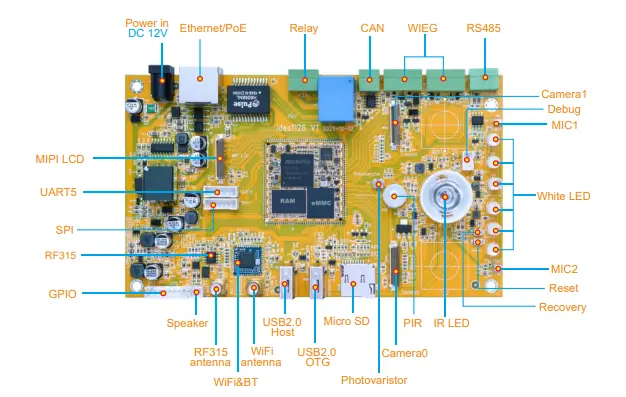
Development Kit (Idea1126)
Ghid de proiectare hardware
Referință pentru circuitul periferic
Circuitul principal de alimentare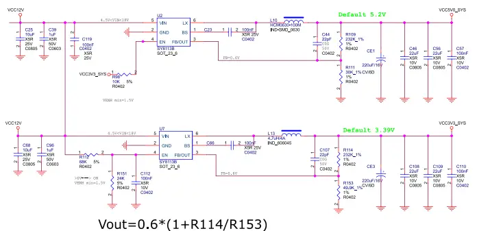
Circuit de depanare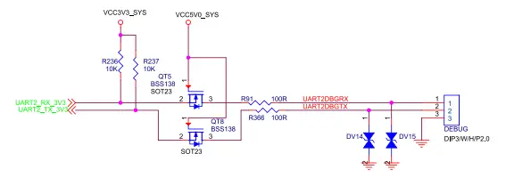
Circuit de interfață USB OTG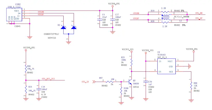
Amprenta PCB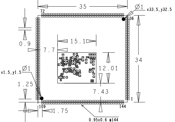
Caracteristicile electrice ale produsului
Disiparea și temperatura
| Simbol | Parametru | Min | Tip | Max | Unitate |
| VCC3V3_SYS | Sistem IO
Voltage |
3.3-5% | 3.3 | 3.3 + 5% | V |
| Isys_in | VCC3V3_SYS curent de intrare | 850 | mA | ||
| Ta | Temperatura de operare | -20 | 70 | °C | |
| Tstg | Temperatura de depozitare | -40 | 85 | °C |
Fiabilitatea testului
| Test de funcționare la temperatură ridicată | ||
| Cuprins | Funcționare 8 ore la temperaturi ridicate | 55 ° C ± 2 ° C |
| Rezultat | TBD |
| Test de viață de funcționare | ||
| Cuprins | Funcționarea în cameră | 120h |
| Rezultat | TBD |
Garanție limitată
Boardcon warrants this product to be free of defects in material and workmanship for one year from the date of purchase. During this warranty period, Boardcon will repair or replace the defective unit by the following process: A copy of the original invoice must be included when returning the defective unit to Boardcon. This limited warranty does not cover damages resulting from lightning or other power surges, misuse, abuse, abnormal conditions of operation, or attempts to alter or modify the function of the product. This warranty is limited to the repair or replacement of the defective unit. In no event shall Boardcon be liable or responsible for any loss or damages, including but not limited to any lost profits, incidental or consequential damages, loss of business, or anticipatory profits arising from the use or inability to use this product. Repairs made after the expiration of the warranty period are subject to a repair charge and the cost of return shipping. Please contact Boardcon to arrange for any repair service and to obtain repair charge information.
Întrebări frecvente
Î: Cum pot actualiza memoria DDR pe CM1126B-P?
A: The CM1126B-P supports up to 4GB LPDDR4 memory. To upgrade, ensure compatibility with the specifications and follow recommended procedures.
Î: Care este necesarul de alimentare pentru CM1126B-P?
A: The power requirement for CM1126B-P is DC 3.3V. Ensure to provide a stable power supply within this range for optimal performance.
Î: Pot extinde capacitatea de stocare a eMMC pe CM1126B-P?
A: Yes, the eMMC storage on CM1126B-P can be expanded up to 256GB. Ensure compatibility with supported storage devices before upgrading.
Documente/Resurse
 |
Sistem integrat Boardcon CM1126B-P pe modul [pdfManual de utilizare V2.20250422, CM1126B-P Sistem pe modul, CM1126B-P, Sistem pe modul, Modul |