
1. Produs terminatview
The Weuaste Professional Backup Camera is designed to enhance vehicle safety by providing a clear, wide-angle view of the area behind your vehicle. This system assists drivers in parking, reversing, and navigating tight spaces, effectively reducing blind spots. It is suitable for a variety of vehicles, including cars, pickup trucks, SUVs, RVs, and vans.

Image 1.1: The Weuaste Professional Backup Camera, a compact and durable device designed for vehicle rear-view asistenţă.

Image 1.2: Visual comparison illustrating the improved safety and reduced blind spots when reversing with a backup camera versus without one.
2. Caracteristici cheie
- High-Definition Sensor: The camera features a high-definition sensor for clear and accurate color reproduction in both day and night conditions. Please note that a monitor or radio with RCA/AV input is required and not included with this product.
- Durable Metal Construction & IP69K Waterproof: Constructed with a durable metal housing, this camera is designed for stability and longevity. It features an IP69K waterproof rating and a fully sealed design to prevent water, fog, or mist intrusion.
- Multi-functional Switching Loops: The camera includes multi-functional switching loops for customizable settings. These include:
- Sârmă albastră: Default AHD video output; cut to switch to CVBS.
- Sârmă albă: Default parking guideline display; cut to disable guidelines.
- Sârmă verde: Default rear view; cut to switch to front view.
- Compatibilitate largă cu vehiculele: This backup camera is compatible with most DC 12-24V vehicles, including cars, pickup trucks, SUVs, vans, and RVs. It offers enhanced night vision capabilities and a 170-degree wide viewunghiul de virare pentru a minimiza unghiurile moarte.
- Easy and Discreet Installation: Designed for versatile installation, the camera can be mounted in various locations such as under side mirrors, on the front bumper, grille, rear decklid, fender, tailgate handle, or trunk lid. Its compact, OEM-style design allows for discreet placement.

Image 2.1: Illustration of the camera's night vision capability and the use of different sized gaskets (5°, 8°, 10°) to adjust the viewunghiul de ing.
3. Conținutul pachetului
Vă rugăm să verificați dacă toate articolele enumerate mai jos sunt incluse în pachetul dumneavoastră:

Image 3.1: All components included in the Weuaste Professional Backup Camera package.
- Cameră (1 unitate)
- 20 Ft Extension Wire (1 unit)
- Double Tape (1 unit)
- M8 304 Stainless Nut (1 unit)
- Panel Remover (1 unit)
- Electrical Adhesive Tape (1 roll)
- Gaskets (3 units)
- Zip Ties (multiple)
- Manual de utilizare (1 unitate)
4. Ghid de instalare
This section outlines the general steps for installing your Weuaste backup camera. Installation may vary slightly depending on your vehicle and monitor type.
4.1 Schema electrică
Refer to the diagram below for connecting the camera to your vehicle's head unit or monitor.
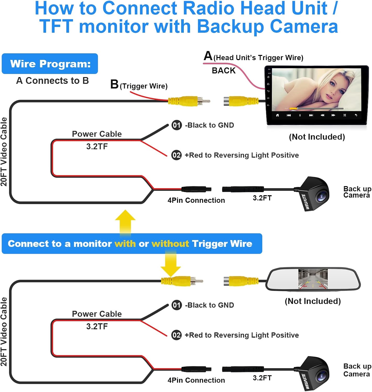
Image 4.1: Detailed wiring diagram showing connections for a head unit with a trigger wire and a monitor without a trigger wire.
Connection to a Head Unit (with Trigger Wire)
- Connect the camera's 4-pin connector to the 20FT Video Cable.
- Connect the black wire (01) from the camera's power cable to a ground (GND) point on your vehicle.
- Connect the red wire (02) from the camera's power cable to the positive terminal of your vehicle's reversing light.
- Connect the yellow RCA video output from the 20FT Video Cable to the 'BACK' video input on your head unit.
- Connect the red trigger wire (A) from the 20FT Video Cable to the head unit's trigger wire (B). This signals the head unit to switch to the backup camera view când treapta de marșarier este cuplată.
Connection to a Monitor (without Trigger Wire)
- Connect the camera's 4-pin connector to the 20FT Video Cable.
- Connect the black wire (01) from the camera's power cable to a ground (GND) point on your vehicle.
- Connect the red wire (02) from the camera's power cable to the positive terminal of your vehicle's reversing light.
- Connect the yellow RCA video output from the 20FT Video Cable directly to the video input on your monitor. The monitor will display the camera feed when it receives power from the reversing light circuit.
4.2 Montarea camerei
The camera's compact design allows for flexible mounting. Use the provided M8 304 stainless nut and double tape for secure attachment. Consider locations such as:
- Under/to your side mirror
- Front bumper or grille
- Rear decklid, fender, or tailgate handle
- Trunk lid (for SUVs)
Ensure the camera has a clear line of sight and is securely fastened to prevent movement.
5. Funcționare
5.1 Multi-functional Settings
The camera features customizable settings accessible via specific wires. These wires can be cut to change the camera's behavior. Perform these modifications before final installation and ensure proper insulation of cut wires with electrical tape.

Image 5.1: Visual guide for modifying camera functions by cutting specific wires.
- Blue Wire (Video Output Mode): By default, the camera outputs AHD video. To switch to CVBS video output, cut the blue wire.
- White Wire (Parking Guidelines): By default, parking guidelines are displayed on the screen. To turn off the parking guidelines, cut the white wire.
- Green Wire (View Direction): By default, the camera provides a rear view. To switch to a front view, cut the green wire.
5.2 Reglarea Viewing Angle with Gaskets
The included gaskets allow for fine-tuning the camera's viewing angle to best suit your vehicle and mounting position. Select the appropriate gasket (5mm, 8mm, or 10mm) to achieve the desired tilt.
Image 5.2: Illustration of the three different sized gaskets (5mm, 8mm, 10mm) used to adjust the camera's viewunghiul de ing.
6. Depanare
6.1 Distorted or No Image After Installation
If your screen displays a distorted image or no image at all after installation, particularly a blue, static-like screen when reversing, it may indicate an incompatibility with the video output format (AHD vs. CVBS).

Imaginea 6.1: Example of a distorted screen and the solution to cut the blue wire to switch to CVBS mode.
Soluţie: Cut the blue wire on the camera's cable. This will switch the video output from AHD to CVBS mode, which is compatible with a wider range of monitors and head units. After cutting the wire, insulate it properly with electrical tape and test the camera again by engaging reverse gear.
7. Specificațiile produsului
| Caracteristică | Caietul de sarcini |
|---|---|
| Dimensiunile produsului | 5.12 x 3.15 x 2.2 inci (5.12" L x 3.15" l x 2.2" Î) |
| Greutatea articolului | 8.1 uncii |
| Culoare | Negru |
| Dispozitive compatibile | Monitorizați |
| Tip de instalare | Montare pe tabloul de bord, montare pe suprafață |
| Voltage | 12-24 volți DC |
| Tehnologia senzorilor optici | CMOS |
| Tip de lentile | Unghi larg |
| Unghiul real al View | 170 de grade |
| Tip conector | RCA |
| Evaluare rezistentă la apă | IP69K |
8. Garanție și asistență pentru clienți
Weuaste provides a 1-year warranty and lifetime technical support for this product. Our products undergo quality testing before shipment to ensure reliability.
For any inquiries, technical assistance, or warranty claims regarding your backup camera, please contact us through Amazon. We are committed to customer satisfaction and aim to respond to all questions within 24 hours.