
1. Introducere
This manual provides detailed instructions for the safe and effective operation of the MCH OS-3040A 40MHz Dual Channel Analogue Oscilloscope. The OS-3040A is designed for laboratory and testing applications, featuring a 6-inch rectangular screen with an internal graticule and multiple display modes for waveform analysis. Please read this manual thoroughly before using the instrument.
2. Informații de siguranță
To prevent electric shock or personal injury, and to avoid damage to the instrument or connected equipment, observe the following safety precautions:
- Împământați instrumentul: Ensure the oscilloscope is properly grounded using the supplied power cord.
- Sursa de alimentare: Connect the instrument to a power source within the specified voltage range (110V/220V AC, 50/60Hz).
- Evitați condițiile umede: Do not operate the oscilloscope in wet or damp medii.
- Nu operați cu defecțiuni suspectate: If the instrument appears damaged or is not operating correctly, do not use it. Refer servicing to qualified personnel.
- Ventilare: Asigurați o ventilație adecvată pentru a preveni supraîncălzirea. Nu blocați orificiile de ventilație.
- Use Proper Probes: Use only probes rated for the voltage and current of the measurement.
3. Conținutul pachetului
Verify that all items listed below are included in your package. If any items are missing or damaged, contact your supplier.

Figura 3.1: Accesorii incluse. This image displays the standard accessories: a power cord, a user manual, a screwdriver with color-coded rings, and two oscilloscope probes.
- MCH OS-3040A Analogue Oscilloscope Unit
- Cablu de alimentare
- Manual de utilizare
- Oscilloscope Probes (x2)
- Adjustment Tool (Screwdriver)
4. Produs terminatview
The MCH OS-3040A is a 40MHz dual-channel analogue oscilloscope. Familiarize yourself with the main components and controls.
4.1 Panoul frontal
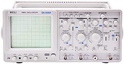
Figura 4.1: Panou frontal. This image shows the front panel of the oscilloscope, featuring the CRT display on the left and various control knobs and input connectors on the right.
- CRT Display: 6-inch rectangular screen with internal graticule (8x10 divisions).
- Vertical Controls (CH1/CH2): VOLTS/DIV, POSITION, AC/DC/GND coupling, MODE (CH1, CH2, DUAL, ADD).
- Controale orizontale: TIME/DIV, POSITION, X-Y mode.
- Trigger Controls: LEVEL, MODE (AUTO, NORM, TV-V, TV-H), SOURCE (CH1, CH2, LINE, EXT), COUPLING (AC, DC, HF REJ, LF REJ).
- Conectori de intrare: CH1, CH2, EXT TRIG.
- Calibration Output: For probe compensation.
- Întrerupător: Control pornit/oprit.
4.2 Panoul din spate

Figura 4.2: Panoul din spate. This image shows the rear panel of the oscilloscope, including the power input, fuse holder, and various warning labels.
- Intrare alimentare CA: Conector pentru cablul de alimentare.
- Suport siguranță: Conține siguranța de protecție.
- Voltage Selector: Allows selection between 110V and 220V AC operation.
- Z-AXIS Input: For external intensity modulation.
- CAL Output: Calibration signal output.
5. Configurare
- Despachetarea și inspecția: Carefully remove the oscilloscope from its packaging. Inspect the instrument for any signs of physical damage.
- Conexiune de alimentare:
- Asigurați-vă că întrerupătorul de alimentare este în poziția OPRIT.
- Verificați voltage selector on the rear panel matches your local power supply (110V or 220V).
- Connect the supplied power cord to the AC power input on the rear panel and then to a grounded power outlet.
- Conexiunea sondei: Connect the oscilloscope probes to the CH1 and/or CH2 input BNC connectors on the front panel.
- Compensarea sondei: Before taking measurements, compensate your probes. Connect the probe tip to the CAL output terminal and the ground clip to the ground terminal. Adjust the probe's compensation trimmer (usually on the probe body) until a stable, square waveform is displayed on the screen.
6. Instrucțiuni de utilizare
This section outlines the basic operation of the MCH OS-3040A oscilloscope.
6.1 Pornirea și afișarea inițială
- Porniți întrerupătorul de alimentare.
- Allow a few moments for the display to stabilize. Adjust the INTENSITY and FOCUS knobs for a clear trace.
- Set the vertical MODE to CH1, horizontal TIME/DIV to a mid-range setting (e.g., 1ms), and trigger MODE to AUTO.
6.2 Vertical System (CH1, CH2)
- VOLTS/DIV: Selects the vertical sensitivity (voltage per division). Rotate to adjust the amplitude of the displayed waveform.
- POZIŢIE: Moves the waveform vertically on the screen.
- AC/DC/GND Coupling:
- AC: Blocks DC components, displaying only the AC portion of the signal.
- DC: Displays both AC and DC components of the signal.
- GND: Disconnects the input signal and grounds the input amplifier, displaying a zero-volt reference line.
- Mod de administrare: Selects the display mode for multiple channels.
- CH1: Displays only the signal from Channel 1.
- CH2: Displays only the signal from Channel 2.
- DUAL (ALT/CHOP): Displays both CH1 and CH2.
- ALT (Alternate): Displays channels alternately, suitable for higher frequencies.
- CHOP (Chopped): Displays channels by rapidly switching between them, suitable for lower frequencies.
- ADĂUGA: Displays the algebraic sum of CH1 and CH2 signals.
6.3 Horizontal System
- TIME/DIV: Selects the horizontal sweep speed (time per division). Rotate to adjust the time scale of the displayed waveform.
- POZIŢIE: Moves the waveform horizontally on the screen.
- Mod XY: Used for displaying Lissajous figures or phase relationships between two signals. CH1 typically controls the X-axis, and CH2 controls the Y-axis.
6.4 Trigger System
The trigger system synchronizes the horizontal sweep with a specific point on the input signal, providing a stable waveform display.
- NIVEL: Reglează volumultage level at which the trigger occurs.
- Mod de administrare:
- MAȘINĂ: Provides a free-running sweep if no trigger signal is present, ensuring a trace is always visible.
- NORM (Normal): Requires a trigger signal to initiate a sweep. If no trigger is present, no trace will be displayed.
- TV-V (TV-Vertical): For triggering on vertical sync pulses of video signals.
- TV-H (TV-Horizontal): For triggering on horizontal sync pulses of video signals.
- SURSĂ: Selects the signal source for triggering.
- CH1: Triggers from the Channel 1 signal.
- CH2: Triggers from the Channel 2 signal.
- LINIA: Triggers from the AC power line frequency.
- EXT: Triggers from an external signal connected to the EXT TRIG input.
- CUPLARE: Determines how the trigger signal is coupled.
- AC: AC couples the trigger signal, blocking DC components.
- DC: DC couples the trigger signal, including DC components.
- HF REJ (High Frequency Reject): Filters out high-frequency components from the trigger signal.
- LF REJ (Low Frequency Reject): Filters out low-frequency components from the trigger signal.
7. Întreținere
- curatenie: Clean the exterior of the oscilloscope with a soft, damp cloth. Do not use abrasive cleaners or solvents. Ensure the instrument is powered off and unplugged before cleaning.
- Înlocuirea siguranței: If the oscilloscope does not power on, check the fuse located on the rear panel. Replace it only with a fuse of the same type and rating. Refer to the specifications for fuse details.
- Depozitare: Store the oscilloscope in a clean, dry environment, away from direct sunlight and extreme temperatures.
- Service: Internal adjustments or repairs should only be performed by qualified service personnel.
8. Depanare
| Problemă | Cauza posibila | Soluţie |
|---|---|---|
| Fără afișaj/Fără alimentare | Power cord disconnected, fuse blown, power switch off. | Check power cord connection, replace fuse if necessary, ensure power switch is ON. |
| No trace on screen | INTENSITY too low, FOCUS out of adjustment, POSITION off-screen, trigger MODE set to NORM with no signal. | Adjust INTENSITY and FOCUS, center POSITION controls, set trigger MODE to AUTO or ensure a valid trigger signal is present. |
| Formă de undă instabilă | Incorrect trigger settings (LEVEL, MODE, SOURCE, COUPLING), probe compensation incorrect. | Adjust trigger LEVEL, MODE, SOURCE, and COUPLING. Perform probe compensation. |
| Forma de undă distorsionată | Incorrect VOLTS/DIV or TIME/DIV settings, probe attenuation mismatch, input signal exceeding limits. | Adjust VOLTS/DIV and TIME/DIV. Ensure probe attenuation matches oscilloscope setting. Verify input signal is within instrument limits. |
9. Specificații
The following are the technical specifications for the MCH OS-3040A Analogue Oscilloscope:
| Parametru | Caietul de sarcini |
|---|---|
| Model | OS-3040A |
| Lățimea de bandă | 40 MHz (Vertical) |
| Canale | Canal dublu |
| CRT Display | 6-inch Rectangular, Internal Graticule, 8x10 divisions (1 div = 1 cm) |
| Sensibilitate verticală | 5mV/div to 5V/div (10 steps) |
| Timpul de creștere | ≤17.5 ns |
| Impedanta de intrare | 1 MΩ ±2%, 25 pF ±5 pF |
| Vol. Maxim de intraretage | 400 V (vârf DC+AC) |
| Moduri de afișare | CH1, CH2, DUAL (ALT/CHOP), ADD |
| Horizontal Sweep Time | 0.2 µs/div to 0.5 s/div (20 steps) |
| Mărire măturare | x10 |
| X-Y Phase Difference | ≤3° DC-50 kHz |
| Moduri de declanșare | AUTO, NORM, TV-V, TV-H |
| Sursa de declanșare | CH1, CH2, LINE, EXT |
| Cuplajul declanșatorului | AC, DC, HF REJ, LF REJ |
| Calibration Output | 0.5 Vp-p ±10%, 1 kHz ±20% |
| Alimentare electrică | 110V/220V AC ±10%, 50/60Hz |
| Consumul de energie | Aproximativ. 40 W |
| Dimensiuni (L×A×D) | 310 × 130 × 370 mm |
| Greutate | 8.5 kg (Net) |

Figura 9.1: Specificații detaliate. This image provides a comprehensive table of technical specifications for the OS-3040A model.
Notă: Specificațiile pot fi modificate fără notificare prealabilă.
10. Garanție și asistență
For warranty information, technical support, or service inquiries, please contact your authorized MCH dealer or the point of purchase. Keep your purchase receipt as proof of purchase for warranty claims.